Reference · Italy · 2025
SNCR upstream of an SCR: 18.7 MW waste-to-energy plant – Italy
Urea SNCR system added to a waste-to-energy plant already fitted with catalytic reduction (SCR). The result is two-stage NOx reduction: the SNCR works in the combustion chamber and lightens the load on the catalyst.
The project
The waste-to-energy plant recovers energy from waste with a grate furnace line of about 18.7 MW, permitted for 30,000 tonnes a year of municipal and non-hazardous special waste. The heat produced generates steam for a turbine that produces electricity.
The plant already had an SCR system with catalyst, which ensures compliance with the NOx limits. The operator asked to add an SNCR system, with urea injected directly into the combustion chamber, as flexible operating support upstream of the catalyst. Ecotherm built it as a compact system, installed with no structural work on the boiler.
How the two stages work
First stage: SNCR in the combustion chamber
Two atomising lances inject urea into the furnace zone where the flue gas is within the temperature window useful for the reaction with NOx, between 850 and 950 °C. The lances work with compressed atomising air and are cooled by a dedicated blower.
Second stage: existing SCR
The downstream catalyst completes the reduction. With part of the NOx already reduced by the SNCR, the SCR works with a lower load; any ammonia not reacted in the furnace is used in the catalyst instead of reaching the stack.
Dosing and control
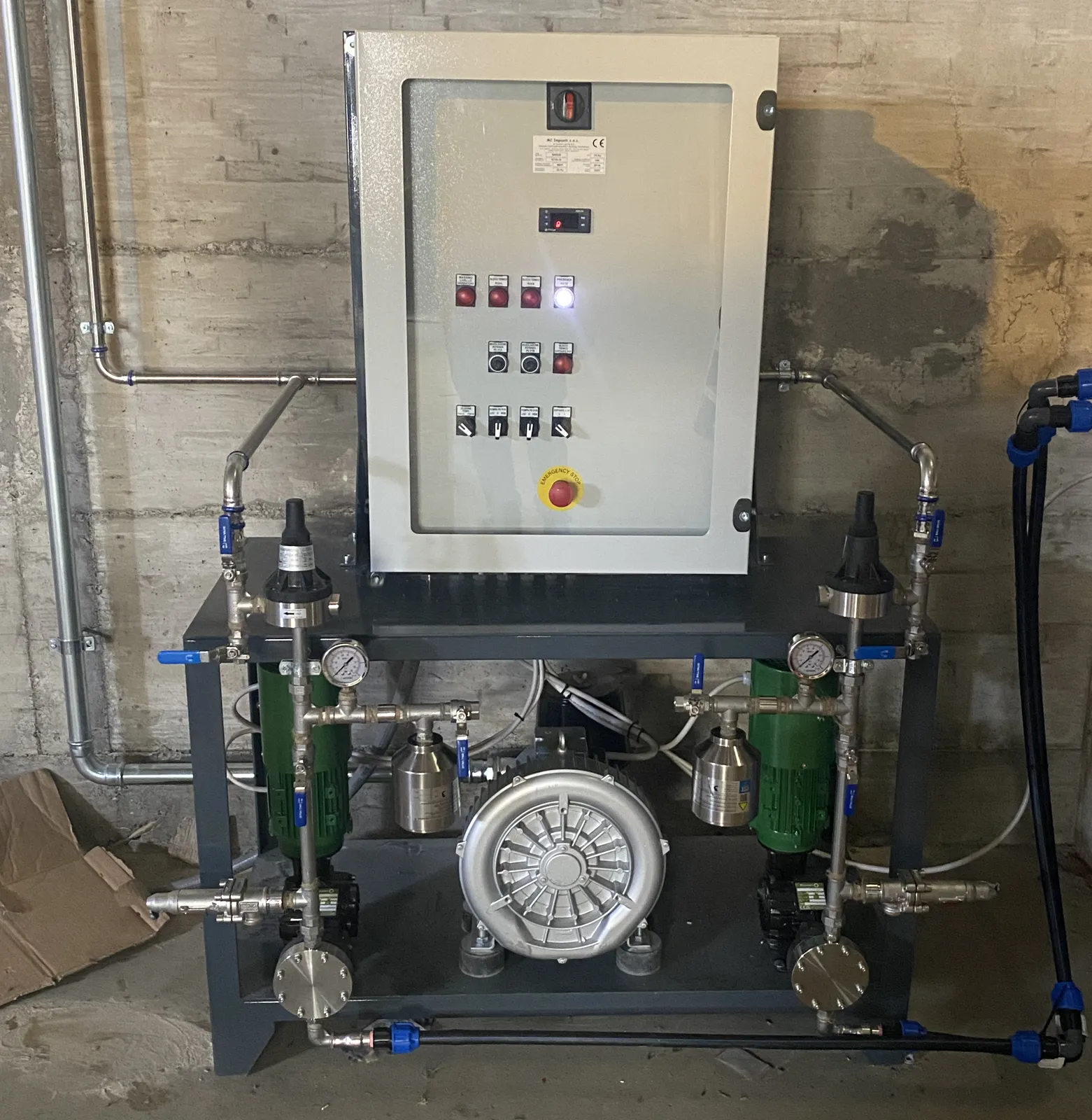
The skid carries two metering pumps with safety valves and the electrical control panel. Urea is injected without dilution. Dosing is adjusted manually or automatically, with the 4–20 mA signal from the NOx analyser.
Further reading
The differences between the two technologies, and when it pays to combine them, are explained in our SNCR and SCR guide.
Scope of supply
- Dosing skid: support frame, two metering pumps with safety valves, pre-assembled in the workshop
- Control panel: electrical panel mounted on the skid, manual control or 4–20 mA signal from the analyser
- Injection: 2 atomising lances with pressure gauges and flow meters
- Lance cooling: blower with safety valve
- Piping: stainless steel where in contact with urea, from the skid to the lances
- Installation, start-up and configuration: hydraulic and electrical systems
Video
Lance function test
Before insertion into the furnace, each lance is tested with water: we check the spray pattern, the fineness of atomisation and the tightness of the fittings.
It is the same spray that, in operation, distributes urea into the flue gas at the right temperature for the reaction with NOx.
Already have an SCR and want to reduce the load on the catalyst?
Send us the furnace data and details of your existing system: we will assess together whether an upstream SNCR can help.